Wiring Diagrams for Receptacle Outlets
by: Dale Cox
Check permit requirements before beginning electrical work.
How to read these diagrams.
This page contains wiring diagrams for most household receptacle outlets you will encounter including: grounded and ungrounded duplex outlets, ground fault circuit interrupters (GFCI), 20amp, 30amp, and 50amp receptacles for 120 volt and 240 volt circuits.
Wiring a Grounded Duplex Receptacle Outlet
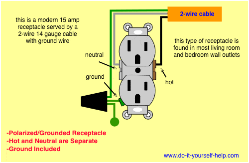
This is a standard 15 amp, 120 volt wall receptacle outlet wiring diagram. This is a polarized device. The long slot on the left is the neutral contact and the short slot is the hot contact. A grounded contact at the bottom, center is crescent shaped. Don't use this receptacle when no ground wire is available. This receptacle can typically be found in living room and bedroom wall outlets. One of these may be controlled with a switch and/or wired to other outlets in the circuit. For a 15 amp receptacle like this, 14/2 cable with ground should be used to feed the circuit.
Wiring an Ungrounded, Polarized Outlet
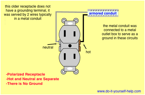
This is an older version of the receptacle in the first diagram. The slots are different sizes to accept polarized plugs but it lacks a grounding slot. This outlet does not make use of a ground wire and there is no protection against electrocution as provide by the grounded receptacle above. When replacing an ungrounded, polarized receptacle use this type and not the grounded type previously mentioned unless it is grounded by a jumper wire to a metal outlet box that is tied to the house service panel ground through a continuous metal conduit. Here the circuit wires are contained in a spiral metal conduit known as an armored cable. A small wire is sometimes spun in with the metal spiral and connected to the metal outlet box to provide grounding.
Wiring an Ungrounded, Non-Polarized Outlet
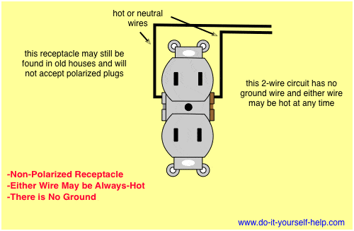
This is the oldest version of a wall receptacle that you will find. It lacks a grounding contact and the plug slots are both the same size. These devices did not make use of a ground wire and both plug slots were treated the same with regard to polarity. The wires used with these outlets were usually both black. With this configuration any wire in the circuit may be hot at all times and there's no protection against electrocution. When replacing an ungrounded device in an older circuit like this, use the polarized one above and not the grounded receptacle at the top unless it is grounded to a metal outlet box that is itself grounded to the house electrical system through a continuous metal conduit.
Wiring a Ground Fault Circuit Interrupter
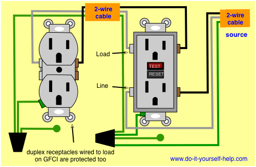
This diagram illustrates a GFCI, or ground fault circuit interrupter, receptacle in a 15 amp circuit. These devices are available in both 15 and 20 amp. A GFCI has two sets of separated terminals: the line terminals and the load terminals. The source from the circuit will always be connected to the line terminals. Any standard duplex outlet or other device connected to the load terminals on this device will be protected by this GFCI. In a kitchen where only one outlet box is available and both a switch for a garbage disposal and a GFCI receptacle are needed, a switch/gfci combo can be used as in the diagram at this link.
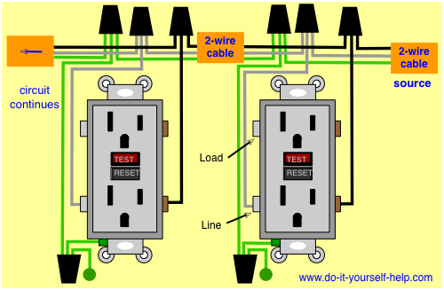
To wire more than one GFCI receptacle in the same circuit, connect the source to the line terminals on each device using a pigtail splice. The load terminals are not used for this circuit. See more GFCI wiring diagrams at this link.
Wiring Diagram for a 20-Amp 120-Volt Duplex Receptacle
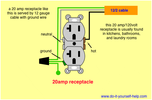
A 20 amp, 120v duplex receptacle outlet like this should be installed in a circuit using 12 awg cable and a 20 amp circuit breaker. These receptacles are usually found in kitchen wall outlets where two branch circuits are needed to serve small appliances and a refrigerator separately. When using this device for heavy appliances like washing machines and microwaves, it should be connected to a dedicated 20-amp/120-volt circuit breaker. As of 2014, a GFCI receptacle is now required in a laundry room for the washing machine.
Wiring a 20-Amp 240-Volt Appliance Receptacle
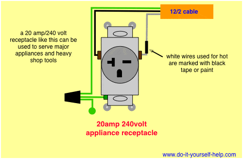
This outlet is commonly used for a heavy load such as a large air conditioner. The outlet should be wired to a dedicated 20-amp/240-volt circuit breaker in the service panel using 12|2 awg cable. With this wiring, both the black and white wires are used to carry 120 volts each and the white wire is wrapped with electrical tape to label it hot. This circuit doesn't make use of a neutral wire and the ground wire is connected to the ground terminal on the device. The slots are configured to accept only plugs from compatible appliances.
Wiring a 30-Amp 240-Volt Outlet
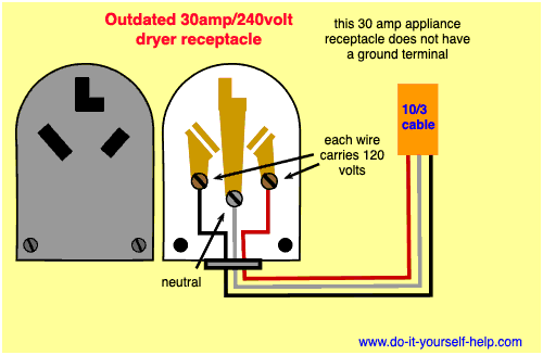
A 30 amp circuit was once the norm for large, high voltage appliances like clothes dryers and kitchen ranges. These receptacles are no longer permitted in new installations but are still in use where they already exist.
This receptacle provides 240 volts and 30 amps service. A 3-wire cable is needed to carry two 120 volt wires and a neutral return for a total of 240 volts. This arrangement makes it possible to power the heating elements in the appliance using the two 120 volts combined and 120 volt alone to power timers and lights. The smallest cable allowed for use with a 30-amp circuit is 10 gauge but 8 gauge may also be found in one of these circuits. The circuit is wired to a dedicated 30 amp circuit breaker.
Wiring Diagram for a 30-Amp Dryer Outlet
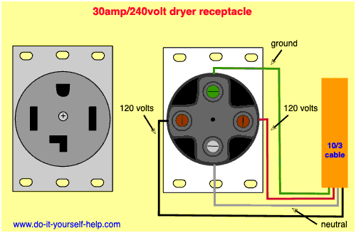
This is a newer version of the outdated 30 amp receptacle appearing in the previous diagram. This circuit is used for a new clothes dryer outlet installation. This receptacle has a ground connection not found in the older 30 amp circuit for added protection against electrocution. A 30 amp outlet like this requires 10/3 cable with ground. The cable contains two 120 volt wires, a neutral wire and a ground wire. This receptacle is connected to a dedicated 30 amp circuit breaker and provides a total of 240 volts to power the dryer heating elements and 120 volts to power lights and other features of the appliance.
Wiring a 50-Amp, 240-Volt Appliance Outlet
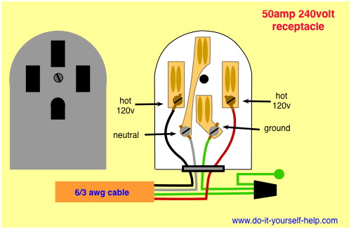
This wiring diagram is used for 50 amp appliance outlet. The receptacle should be wired to a dedicated 50 amp circuit breaker using 6 awg cable. The 50 amp circuit is required for new installations of some large appliances requiring 240 volts. Two wires carrying 120 volts each can be combined to provide high voltage to heating circuits and one of the 120 volt wires can serve lights or other low voltage circuits in the appliance. The neutral wire provides a return path for the circuit and the ground wire provides extra protection from electrocution not found on older 30 amp, 240 volt appliance hookups.
 Wiring Multiple Receptacles
 Wiring to Add a New Receptacle
 GFCI Receptacle Wiring
 Wiring a Switched Outlet
 Circuit Breaker Wiring
 Diagram GFCI Combo
 Wiring for Two Outlets in One Box
 Wiring to Add a New Light