Wiring Diagrams for Multiple Wall Outlets
by: Dale Cox
Check permit requirements before beginning electrical work.
How to read these diagrams.
This page contains several diagrams for 2 or more receptacle outlets in one circuit. Wiring for multiple ground fault circuit interrupters (gfci) and standard duplex receptacles are included with protected and non-protected arrangements.
Wiring Multiple Outlets in a Series
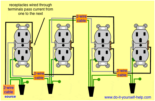
In this diagram wall outlets are wired in a row using the terminal screws to pass voltage from one receptacle to the next. Wiring outlets together using the device terminals, instead of a pigtail splice as shown in the next diagram, can create a weakest-link problem. Using the method illustrated here any break or malfunction at one outlet will likely cause all the outlets that follow to fail as well.
Wiring Diagram for Multiple Outlets
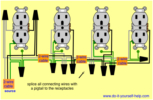
This diagram shows the wiring for multiple receptacles in an arrangement that connects each individually to the source. All wires are spliced to a pigtail which is connected to each device separate from all the others in the row. This wiring allows for source voltage at each outlet independent of the others in the circuit.
Wiring Diagram for Dual Outlets
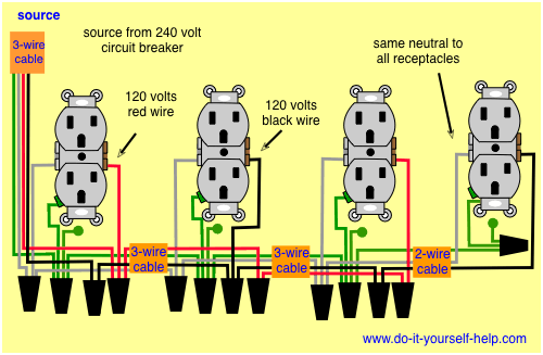
Here 3-wire cable is run from a double-pole circuit breaker providing an independent 120 volts to two sets of multiple outlets. The neutral wire from the circuit is shared by both sets. This wiring is commonly used in a 20 amp kitchen circuit where two appliance feeds are needed, such as for a refrigerator and a microwave in the same location.
Wiring Diagram for Multiple GFCI's
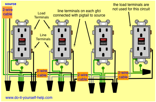
In this diagram multiple ground fault circuit interrupter receptacles are wired together using pigtails to connect the source. Two-wire cable is run between the gfci's, and the hot and neutral wires from the source are spliced to the line terminals at each device. The load terminals are not used and each device provides its own, single-location protection.
Wiring Multiple Outlets and a GFCI
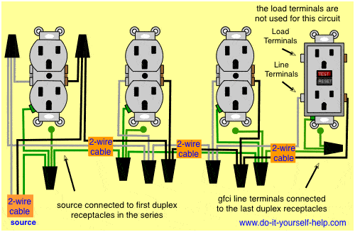
Here a gfci receptacle is added at the end of a row of duplex receptacles for single-location protection. The first outlet is connected to the source and 2-wire cable runs from box to box. All wires are spliced with a pigtail at the devices to pass current to the next. The load terminals on the gfci are not used and it does not protect the other receptacles in the circuit.
Wiring a GFCI to Protect Multiple Outlets
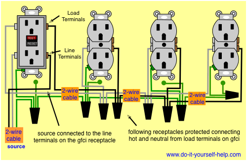
Here one ground fault circuit interrupter protects multiple duplex receptacles coming after it, known as multiple-location protection. Two-wire cable runs from the gfci to all the following outlets. The line terminals on the gfci are connected to the circuit source and the load terminals are connected to each following outlet with a pigtail splice. This keeps each duplex receptacle connected directly to the gfci.
 GFCI Receptacle Wiring
 Wiring to Add a New Receptacle
 Wiring for Wall Outlets
 Wiring for Two Outlets in One Box
 Wiring a Switched Outlet
 Find an Electrical Source